


Parameter: | KV-0 | |||
Output Volume | Max. Pressure (bar) | Each Part Output 1/min | ||
cm3/rev | Mimimum | Recommend flow | Maximum | |
0.25 | 210 | 0.3 | 0.7 | 1.8 |
0.45 | 210 | 0.6 | 1.2 | 3 |
0.57 | 210 | 0.8 | 1.5 | 3.8 |
0.76 | 210 | 1 | 2 | 4.8 |
0.98 | 210 | 1.2 | 2.3 | 5.6 |
1.27 | 210 | 1.5 | 3 | 7.2 |
1.52 | 210 | 1.9 | 3.5 | 8 |
2.3 | 210 | 2.6 | 5 | 10.3 |
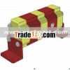
Outlinge and installing dimension
Number of work pieces | 2 | 3 | 4 | 5 | 6 | 7 | 8 | 9 | 10 | 11 | 12 |
Number of filler opening | 1 | 1 | 2 | 2 | 3 | 3 | 4 | 4 | 5 | 5 | 6 |
PS: All the filler openings are inter connected, maximize rate of flow for single filler opening is 15L/min
A. Typically Apply
Synchronous movement:
If several hydraulic motors or hydraulic cylinders drive by single stream of pressure oil but without any way to control their own rate of flow, then the motor or cylinder with the minimum pressure demand would be started up before others until reach its stroke end or meet a greater load to startup next unit with lower pressure requirement. In other words, all the hydraulic motor or hydraulic cylinders will startup one by one until all activities end. Obviously, we don’t want to see such a situation. In reality, we probably meet this condition- working under different loading, and use those methods to control the rate of flow to realize synchronous movement: Proportional valves feedback control, use flow distributing and collecting valve, and gear or plunger type synchronous shunt.
B. Synchronous Error:
For gear synchronous shunt, its synchronization performance depends:
- Load balance
- Medium’s temperature and viscosity
- System pressure rating
- Shunt revolution
- Discharge continuity
C. Demonstration of the type:
KV- Synchronous shunt motor
0: Size 0, 1
D/0: Serial Name/ Output Volume (cubic centimeter/rev)
RV0: 0.25, 0.45, 0.76, 0.98, 1.27, 1.25, 2.3
RV1: 1.2, 2.2, 3.2, 4.3, 5.9, 9.8
25/2: Connection number: 2-12
D. For greater synchronization performance, we suggest the design should follow:
- Rotate speed of shunt:>/= 1000rpm
- The load of all the jacking oil cylinder should equally as far as possible
- Under a steady temperature with working pressure range from 100bar – 210bar, ensure the medium viscosity around 40cst.
- Initial design could refer this synchronization precision:+/- 1.5% - +/-2.5%
E. Internal Step-down
For a gear shunt, pressure loss P of imports and exports is around 10~12bar, but when actually use, influence by the pressure, rate of flow and medium viscosity, the loss of pressure maybe higher the references.
F. Rotate speed range:
Recommend rotate speed: 700~2300rpm
G. Eliminate of synchronous error
As an individual flow control unit, gear shunt inevitable has synchronous error without any way to forbidden. So that for make sure the synchronization precision of system, when design the hydraulic system please make sure the hydraulic cylinder could reach its stroke end every time.
Gear Pump KV0
